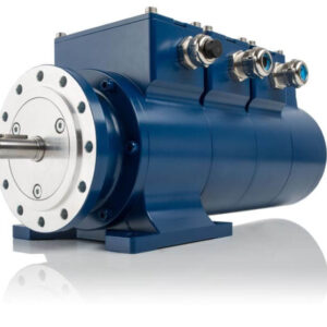
TACHO GENERATOR IMAGE

Understanding Tacho Generators

Huebner Speed Monitoring is a supplier of Tacho Generators. You may know you need them for specific applications and may have even ordered customised units for your own industrial and commercial needs. Still, you may not fully understand the finer details behind their robust technology. Continue reading as we explore the intricacies of one of our product listings: tacho generators.
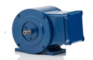
tacho generator

What is a Tacho Generator?

There are many ways to measure the position of a rotary axis. Some position-measuring devices, such as absolute and incremental encoders, can also determine the speed of the axis by evaluating a combination of distance, pulses, and time. However, a tacho generator may be the most suitable option for applications requiring speed measurement only- without position information.

If you have read our blog on Generator Excitation Control Systems, you will recall that a generator converts mechanical energy into electrical energy. The voltage of the generated power is directly proportional to the device’s shaft speed. Tacho generators were specifically designed to ensure that the relationship between voltage and speed remains precise and linear within a specific range.

[1] Tacho generators are true speed-measuring devices that rely on the basic principle of a generator to determine the speed of a rotating part based on voltage. To measure the speed of a device — such as a fan or motor shaft —the tacho generator must be attached to the device itself to evaluate the voltage of the power produced by the generator to determine the device’s rotational speed.

The formulas can be found below:

[2]

Tacho Generator Formula

Types of Tacho Generators

There are two basic types of tachometric generators, namely:

  • A commutator generator
  • A synchronous generator.

[3] Most tacho generators used today are brushed DC types with a permanent magnet stator and a wound, revolving armature. One end of the armature is affixed to the object whose speed is being measured, and the armature revolves within the stator’s magnetic field. As the measured object rotates, the rotation of the tacho generator armature induces a voltage. The amplitude of the voltage is proportional to the speed of rotation.

Commutator Generator

A commutator transforms the alternating current produced by rotation right into direct current that can be analysed by a voltmeter circuit and transformed to speed. If the direction of rotation changes, the voltage polarity modifies, so the DC tacho generator can determine both the speed and direction of rotation.
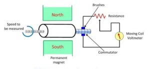
Commutator Generator

Image Source: Circuit Globe

Three-Phase Synchronous Generator

An AC tacho generator does away with brushes and uses a stationary, wound stator and a rotor with permanent magnets. In this case, the rotating magnetic field of the rotor induces voltages in the 3-phase windings of the stator. The amplitude and frequency of the induced voltage are proportional to the rotation speed. The AC output is rectified to a DC voltage whose amplitude is proportional to the rotation speed, and the rectified output goes through a smoothing filter to reduce voltage ripples.

Because AC current changes polarity twice per electrical cycle, an AC tacho generator cannot determine the direction of shaft rotation like a commutator generator. However, they have a greater lifespan because they don’t require mechanical brushes.

Tacho generators are typically used with DC motors and drives in motion control applications to control motor speed.
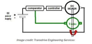
In case you were wondering, your car’s tachometer is a tacho generator with an analog dial or digital display.


TDP/S – Tacho Generators Offered By Huebner Speed Monitoring

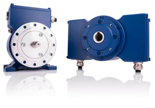
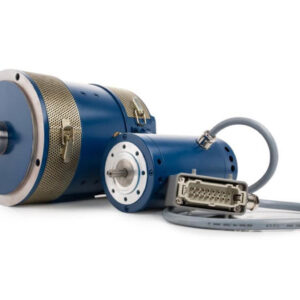
Huebner Speed Monitoring Tacho generators are analogue transducers for instrumentation and control technology. These permanently excited generators form the speed with which they are driven to a voltage proportional to that speed. Thanks to their robust design and construction, they are suitable for larger industrial drives.

Depending on the requirements, the HUBNER GIESSEN Tacho generators are produced in customized sizes and connections and in various voltage versions. They are available with IP ratings IP55 to IP68 and have a temperature compensation of up to +100’c.
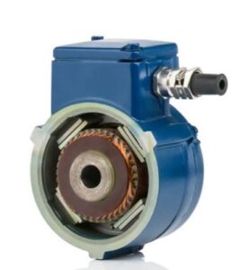
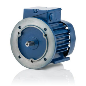
TACHO GENERATOR IMAGE

Contact Huebner Speed Monitoring for all your questions, orders, and enquiries.


References and Research:

[1] [2] https://www.motioncontroltips.com/

Huebner Speed Monitoring Three-Phase Synchronous Generator

Generator Excitation Control Systems

In South Africa, the word “Generator” isn’t unknown. In fact, with the continuous bouts of load shedding, generator and inverter systems bring about a sigh of relief if you have access to them.

We look at a different type of generator, specifically generator excitation control systems. Excitation systems can be defined as a system providing direct current (DC) to the rotor windings of a generator in order to control the strength of its magnetic field.

The four common excitation methods include the following:

  • Shunt or Self Excited
  • Excitation Boost System
  • Permanent Magnet Generator (Three phase synchronous generator)
  • Auxiliary Winding

Huebner Speed Monitoring provides three-phase synchronous generators; let’s take a closer look at this popular excitation method in more detail.

What is Excitation?

There are two main sources of energy conversion: a motor and a generator. Generators convert mechanical energy into electrical energy by moving the electrical conductors in a magnetic field. In order for this conversion to take place, excitation creates the electromagnetic field by means of an electric current to enable the energy conversion.

An electric generator or motor consists of a rotor spinning in a magnetic field. The excitation process provides direct current (DC) to the rotor windings to control the magnetic field’s strength.

Excitation current (DC) is supplied using either brushed or brushless excitation means. However, most modern generators today use brushless excitation since it requires less maintenance.

Three-Phase Synchronous Generator

Three-phase synchronous generators are used in nearly all commercial power plants. The least common type is the induction generator. Three-phase synchronous generators are also known as alternators because they convert the mechanical energy from the prime mover (gas turbine, steam turbine, water turbine, etc.) into electrical energy, as explained above. They are highly efficient thanks to their permanent excitation.

The synchronous generator is a type of AC generator. Popular applications include energy generation in wind turbines, steam turbines, and hydro turbines. A static or rotating magnetic field constructs the synchronous generators used in our industries.

Working Principle of Synchronous Generator

emf= dΦ/dt

  • This law says that the rate of change of flux in any device will produce EMF in that device. If a device is static and the field is rotating, it will also produce a field in the device.
  • In the case of a synchronous generator, the rotor is rotating, producing a field in the stator.

Working Principle of Synchronous Generator

Image Source: theengineeringknowledge.com

Synchronous Generator Construction

  • There is no residual magnetism in a synchronous generator to produce self-excitation.
  • The external DC supply is provided to the rotor, which produces a magnetic field in the rotor. When the rotor is rotated by means of mechanical energy, its field links with the stator windings to produce a voltage in the stator.
  • There are two terms commonly used to describe windings in a machine, namely: armature windings and field windings.
  • The windings that produce the main field in a machine are called field windings, and the windings that produce voltage are called armatures.
  • In the application of a synchronous generator, the field windings are the rotor windings, and the stator windings are the armature windings.

Let’s break down some of these elements making up a three-phase synchronous generator.


Stator Core and Windings

[1] Manufactured from laminate steel, the stator has milled slots along its entire length that are filled with copper conductor windings. Each winding slot is fitted with a wedge to prevent the copper windings from being displaced due to the centrifugal forces created during operation. An alternating current is induced in the stator windings as the rotor’s magnetic fields intersect with the windings.


Rotor and Windings

[2] The rotor consists of solid steel with slots milled along its entire length; the slots are filled with copper conductor windings. Direct current (DC) is supplied to the rotor windings to produce an electromagnetic field around the rotor. As the rotor rotates, the north and south of its magnetic fields will induce alternating current (AC) flow in the stator windings.


Bearings

[3] Bearings support the weight of the shaft when the generator is idle and in operation. Small units may use anti-friction roller bearings, but larger units use plain/sliding bearings. Where plain bearings are used, the lubricating oil pressure must be maintained when the generator is in operation. A reduction in lubrication oil pressure will damage the bearings and shaft.


Cooling System

[4] Cooling is achieved by air, hydrogen, or water. Smaller generators can be air-cooled, but larger units are often hydrogen cooled, while the very large units can be water-cooled.


Frame

[5] The frame houses the stator, rotor, bearings, and cooling channels used by the generator. It provides the structural strength needed to mount all of the components and is designed to absorb vibration.


Bushings

[6] Bushings are used to pass electrical current through the enclosure of the generator without raising the electrical potential of the generator casing. Bushings usually consist of an aluminium or copper central conductor and a porcelain insulator.


Retaining Ring

[7] Retaining rings place residual compression stress upon the rotor windings; this counteracts the centrifugal forces the windings are subjected to when the generator is in operation.


Cooling Fans

[8] Air is drawn through the generator casing using single-stage axial fans; it removes waste heat from the generator casing.

Choosing Huebner Speed Monitoring for Your Three-Phase Synchronous Generator

Well-designed excitation systems provide reliability of operation, stability, and fast transient response. Huebner Speed Monitoring offers just that; a DSG P synchronous generator that is robust, permanently excited, and highly efficient.

Huebner Speed Monitoring Three-Phase Synchronous Generator

Huebner Speed Monitoring Three-Phase Synchronous Generator

Contact Huebner Speed Monitoring for all your questions, orders, and enquiries. Alternatively, click here to learn more.


Resources: 

[1] [2] [3] [4] [5] [6] [7] [8] https://www.theengineeringknowledge.com/introduction-to-synchronous-generator/

https://savree.com/en/encyclopedia/three-phase-synchronous-generator

What is an Incremental Encoder?

Encoders translate rotary or linear motion into a digital signal, which is sent to a controller. The controller monitors motion parameters, including speed, rate, direction, distance, or position. There are different types of encoders available, including absolute encoders and magnetic encoders, but this article will take a closer look into incremental encoders.

An incremental encoder is one of the most popular rotary encoders used. This type of encoder converts the position of a shaft or an angular motion into a digital code or analog to identify motion or position. An incremental encoder can be used in positioning and motor speed feedback applications, including servo/light, industrial or heavy-duty applications.

Incremental encoders are a favorable choice because they provide accurate speed and distance feedback and because there are only a few sensors involved, the systems of incremental encoders are both inexpensive and simple. It is important to note the limitations of incremental encoders; they can only provide change information, so they require a specific reference device in order to calculate motion.


How Does an Incremental Encoder Work?

A specific amount of pulses are provided in one rotation of an incremental encoder. The output can either be:

  • a single line of pulses (an “A” channel)
  • Or two lines of pulses (an “A” and a “B” channel) that are offset to determine rotation. This phasing between the two signals is known as quadrature.

The most common type of incremental encoder uses two lines of pulses or channels (A and B) to sense position. This type of incremental encoder uses two code tracks with the sectors positioned 90° out of phase. The two output channels of the quadrature encoder determine the position and direction of rotation.

A ‘Z’ channel or index can be provided for pulse count verification on the A and/or B channels. This channel can be gated to either A or B in their various states. It can also be un-gated and vary in width.

Below is a video describing how an incremental encoder works:

Incremental Encoders vs. Absolute Encoders


There are several types of encoders available, but they typically fall into two main sensing techniques or categories, namely:

– Linear

– Rotary


Within these categories, there are different encoder measurement types, including:

– Absolute

– Incremental


There are also different electromechanical technologies such as:

– Magnetic

– Optical

– Inductive

– Capacitive

– Laser


If you have heard about absolute encoders, then you may be left wondering if you should use an incremental or an absolute encoder for your specific application.

Absolute rotary encoders can measure “angular” positions, while incremental rotary encoders can measure distance, speed, and position. Incremental encoders are most commonly used to measure the speed of mechanical systems.


Huebner Speed Monitoring Incremental Encoders 

The Huebner Speed Monitoring Incremental Encoders range can be deployed in a wide variety of applications to measure and monitor the speed of standard, auxiliary and secondary drives in steel and rolling mills, mining operations as well as in ports and crane systems.

These encoders are robust and long-lasting and can be used in either a solid or hollow shaft as well as a combination shaft.

The drive chain is protected against the damaging shaft currents when attaching these incremental encoders with an isolated coupling or (with optionally available) isolating hybrid bearings.

The Huebner Giessen Incremental Encoders offer a high signal quality of up to 1 million pulses in HTL, TTL, Sin/Cos, if required, for dynamic feedback control across the entire speed range. The rugged foot construction facilitates the simple attachment of additional encoders at the second shaft end.

If you require incremental encoders, then contact Huebner Giessen SA today. Let us know your requirements, and we will help you find the right solution.

We value our customers - Give us a call today

We are fascinated by technology – and we understand our customers. To support you, we offer robust encoder systems, powerful drive technology and worldwide service.

Exchange solution for tilting angle monitoring

  • Direct mounting / elimination distribution gear
  • Higher accuracy
  • Easy configuration of switching points
  • Fast commissioning and restart after preset

Before: Mechanical cam limit switch and absolute encoder mounted by using an additional distribution gear.

After: Electronic position switches and absolute encoder in one unit directly mounted without distribution gear.

In steel making plants tilting angles of converters are measured by absolute encoders and monitored by mechanical cam limit switches.

The sensors are normally mounted by using an additional distribution gear, which causes mechanical play and inaccuracy. Furthermore, the mechanical cam limit switches are difficult to preset and not precise enough.

The universal encoder system U-ONE-(SAFETY-) Compact provides the same outputs as the old solution, but in just one compact and robust unit:

  • Absolute encoder
  • Electronic position switches

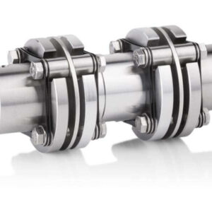
The unit can be mounted directly to the application shaft without using any distribution gear. For this Hübner Giessen provides special torsion resistant double-joint couplings. The switching points are easy to configure and the system can be restarted fastly after preset.

Optionally available with safety certification SIL 2 / PL d.

Robust encoders

  • Greater functional component reliability
  • Higher converter plant availability
  • More precise measurement signals despite shock and vibration loads
  • Easy and time-saving programming

Before: Old skip-car control mechanism with two mechanical geared cam limit switches.

After: More precise signals because of robust combination of bearing block and heavy duty encoders

The skip-car control mechanism utilized to date included two mechanical, geared cam limit switches that are time consuming to program. The mechanical overspeed switch utilized can prove problematical when subjected to shock and vibration loads. Neither of these components exhibits the required precision and as such are not suitable to meet the modern-day requirements of steel mill operations.

Upgrading to meet modern demands required suitable components for measuring actual values that are not only characterized by their high accuracy and functional reliability, but are also easy to program. Hübner Giessen replaced one of the geared cam limit switches with a series FG 4 K incremental encoder and an AMS 4 K type absolute encoder with integrated SSI interface. Fitting the devices to a bearing block increases their resistance to shock and vibration loads and compensates the mechanical tolerances of the installed, previous transfer gearbox. The other cam limit switch will also be replaced in a second modernizing step as will the mechanical overspeed switch be replaced by a programmable electronic overspeed switch.

In any case you can count on our support for the complete project.
From the first discussion to the installation support on site.


94 / Metals / Converter / Hoist
Case Studies


GN series motors

  • Rugged DC shunt-wound motors feature infinitely variable control
  • Designed for 20 journeys per shift (8h)
  • Short-term 3-fold overload permissible
  • Battery powered, automated guided vehicle system

Heavy-load transporters are used to transport the casting ladles from the warehouse to the casting house.

Battery powered and robust DC shunt-wound motor GN 17.17.4 for trouble-free operation without trailing cable.

Infinitely variable DC motors are required to drive a 100 ton heavy-load transport vehicle used to transport casting ladles. The motors are powered by a 48 V battery and connected to a gearbox to provide a travelling speed of 10 m / min. They must be able to provide full torque across the entire speed range combined with a possible short-term 3-fold overload capability. The vehicles are equipped with a battery (capacity 625 Ah) to provide a minimum travelling time of 200 minutes, which is calculated to provide sufficient power for 20 journeys per shift. The motor output is to be dimensioned accordingly.

For each deployed transport vehicle Johannes Hübner Giessen supplied 2 separately excited, low-voltage, shunt-wound DC motors with an integrated spring-loaded brake from its GN 17 series. The motors are equipped with an additional integrated fan to cool the outer surface and are designed for intermittent operation (S3 42 % CDF). The rated motor torque is 17 Nm. The motors are capable of delivering a short-term overload of up to 50 Nm. A BAMOBIL battery controller is included in the Hübner Giessen scope of supply to regulate power to the DC shuntwound motor.


88 / Metals / Casting / Ladle Transporter
Case Studies


Heavy-duty generator DSG P

  • Higher plant availability and productivity
  • No need to change battery (previously every 14 days)
  • Permanent power supply to the sensors ensures higher operating reliability
  • Maintenance-free and long-lasting

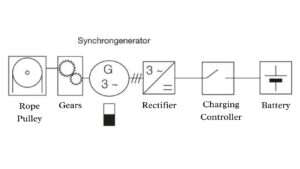
System structure of the self-sufficient energy supply system for the sensors of the pig iron crane.

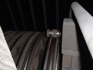
The energy for battery charging is generated from the lifting movement of the crane by a rotating sheave at the rope pulleys.

Special safety sensors are installed in the laminated hooks to monitor if the pig iron ladles are securely attached. The sensors and a radio transmitter required to transmit the sensor signals are installed on the traversing gear of the crane system, and need to be powered by voltage of 12 VDC. Supplying power via a trailing cable is not an option, because the temperature of the pig iron in this area is about 1300 degrees Celsius. Consequently, power is supplied via a 12 V battery that is located on the traversing gear of the crane system. A solution that recharges the battery during operations is sought to avoid failures as well as downtimes resulting from the necessity to date of having to change the battery.

The permanent magnet three-phase synchronous generator DSG P 63.07.4 utilizes the rotating motion of the bull wheels of a lifting beam as a source of energy. The generator is driven via a rotating sheave and speed increasing gearbox with each lifting nd lowering motion of the crane. The generator supplies alternating voltage analogous to the speed; a rectifier converts the AC voltage to DC voltage. The charge controller monitors the charge status and the flow of energy to the battery. Implementing an autonomous auxiliary power supply in the form of well-coordinated overall solution gains valuable production time and safeguards operational reliability. The previous solution of having to change the battery every 14 days is not required any more.


96 / Cranes / Traversing Gear
Case Studies


Hot and Cold Rolling Mills

  • Easy exchange or extension of existing encoder solutions
  • Cost-efficient, as encoders can be exchanged selectively
  • Implementation in the shortest possible time, optionally SIL certified
  • Planning, delivery and mounting support from a single source

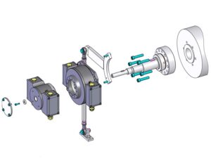
Exploded view

Exploded view

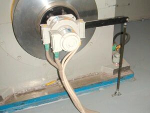
All around the world Hübner Giessen encoder solutions are installed at main drives of Hot and Cold Rolling Mills.

These large motors often run for many years and after a while the question about a possible encoder modernization arises to provide new or additional electrical outputs.

With the encoder solutions implemented by us, the scope for a modernization is limited to a minimum. For example, our FGH 6 and FGH 8 encoders have an integrated mounting flange ex works. Thereby an additional encoder can easily be added to the existing encoder system.

This could be a freely programmable overspeed switch or a universal encoder system with fi ber optic signal transmission (both optionally SIL certified). But also an additional incremental encoder with different pulse rate could be an option.

In any case you can count on our support for the complete project.
From the first discussion to the installation support on site.

Keeping an Eye on Your Equipment

August through to October is known as the windy months in South Africa. We have all born witness to the windstorms currently blowing through the country, bringing with it the much-anticipated rain and summer months.

When the weather acts up, companies in the engineering, agriculture, and mining sectors need to be more vigilant about their equipment.

Encountering a breakdown or potential injury on duty is a large concern to all involved. All equipment must be checked to ensure no potential dangers are looming.

Incidents tend to occur when we turn a blind eye to the operational aspects of a plant. This is a dangerous error to make.

It is critical to the success of any plant and the safety of its employees to run routine safety checks, ensuring that everything is running smoothly.

Mining equipment is put under duress with the workload it produces, resulting in wear and tear to all the bits and pieces keeping the plant going.

A strict maintenance schedule should be implemented to ensure that there is no downtime due to equipment failure.

Strong winds bringing dust and sand into a plant can cause damage to intricate parts of the operation that are not always visible to the naked eye.

To guide you along the safety process, we will provide you with a few tips on successfully maintaining your industrial equipment.


Five Tips to Successfully Maintain Your Mining Equipment


  • Keep machinery lubricated at all times

Any machine is destined to fail without proper lubrication. Lubrication is as important as what the moving parts of the machine are. Lubricating a machine regularly and correctly will alleviate excess friction.

The lifespan and deterioration of a machine are expedited when the correct precautions are not taken seriously and performed regularly.


Too much lubrication will cause errors such as energy loss, damage to seals, and an excess in the accumulation of grease.


Ensure that the correct type of lubrication is applied to each machine so that there are no breakdowns further down the road.

  • Clean heavy machinery well

Heavy machinery is fitted with special seals to protect the intricate parts. If dirt and grime find their way in there, the untrained eye will not detect it. This will lead to catastrophic damage and loss.

Broken or torn seals need to be changed immediately, and the breathers must be kept clean from debris. Filters need to be changed when they are dirty or clogged.

With heavy winds or rain comes dirt and grime. Keeping your machinery covered or indoors will help alleviate the trouble that this can cause.


  • Keep up with regular maintenance.

Conducting an inspection or repair when something goes wrong is not enough for heavy machinery to stay in top condition.


Set up a regular inspection plan with notations taken on any inspection performed previously.

Conduct regular checks on gaskets and seals. Belts and pulleys must also maintain their alignment.


Moving parts, such as gears, should be checked continually to ensure no wear and tear or damage. Proper lubrication needs to be applied to the parts to keep them functioning at optimal levels.


  • Take note of wear and tear.

During normal operations, you may notice some wear and tear occurring to parts or machines. It is imperative to take note of this as it may be a signal of more severe problems, especially on braking systems.

Common signs of wear and tear include heat, vibration, and belt shape.


Overheating can be caused by the incorrect use of lubrication to moving parts. When vibration occurs, there may be some gears or belts that are misaligned.

  • Keep the operators well trained.

One of the most effective ways to ensure your heavy machinery stays operational is to train all staff.

New employees need to go through an intense training process to ensure they know how everything works and what to look for in case of a problem.


Current employees should go through refresher courses and new inductions on any new and improved machines or parts that they may acquire.


Without the proper induction and training, any business runs the risk of downtime or even accidents that can be costly.


Training courses should be scheduled at regular intervals to ensure that all the operators know what they are doing and what to look for when a machine is misbehaving.


If you want to ensure the longevity of your heavy machinery, the tips above will guide you in the right direction.


When you need new equipment, parts, or assistance, Huebner Speed Monitoring is the partner you need. Backed with years of knowledge within the mining and agricultural industries, Huebner will ensure the safety of your workforce, and equipment is their top priority.


They provide each customer with a tailor-made solution. Contact one of their friendly staff today to get the ball rolling on a long and successful business partnership.


Industrial Braking Systems

Being a highly technical product, many of us don’t know the first thing about industrial braking systems besides the fact that brakes stop moving objects like cars. They are a safety mechanism that could potentially be the difference between life and death – whether it be the life of a huma, or the operating lifespan of a machine.

Aside from cars, braking systems are employed in many manufacturing, mining, marine, and engineering businesses powered by heavy machinery. Continue reading as we explore industrial braking systems in further detail.


Back to Basics

Brakes have the sole purpose of absorbing kinetic energy when two surfaces press together to bring an object to a halt.

Functioning at high speeds with large amounts of energy coursing through them, brakes are exposed to significant wear and tear while fulfilling their purpose. They also generate a lot of heat energy as they impose stopping power.

History Lesson

Until half a century ago, braking systems were predominantly drum brakes. Drums resulted in a heat build-up inside the drum during heavy braking sessions.

As a result of the braking system being a drum, there was only one surface from which energy and heat could dissipate.

With the need for a different approach, the automotive industry decided to adopt a disc braking system in the 1970s. Disc brakes meant that the rotor was exposed to outside air when in and out of use, allowing for a more efficient cooling system.

A faster cooling system meant that the brakes were less exposed to fading and overheating challenges. Heat and energy are also dispersed over two rotors as opposed to one drum making them more effective.

In a manufacturing setting, the use of this new braking system has drastically reduced downtime with machine failures.

There has also been a marked improvement in maintenance requirements and efficiency. They have allowed operations to continue smoothly in inhospitable environments.

Now that we are all caught up on the history and the basics of braking systems let’s look at the various types of brakes you are likely to encounter.


Different Types of Braking Systems


  • Hydraulic Brakes

Most commonly used in industrial applications like mining equipment, cranes, and winches, hydraulic brakes use braking fluids to transfer pressure from the control to the brake mechanism.


  • Fail-safe Brakes

Power losses are a common occurrence in South Africa, making this system invaluable to manufacturing plants. Fail-safe brakes are designed to kick into effect when a power interruption happens.


The best example here is an elevator. A great example is the movie Speed, where the elevator cables are severed, but the Fail-safe brakes keep everyone alive by preventing a catastrophic fall.


  • Pneumatic Brakes

Also known as an air brake, pneumatic brakes make use of compressed air stored in a reservoir. A valve will allow compressed air to flow through and engage the brake when the lever or pedal is actuated.


Think about those times you are stopped at a robot, and the truck next to you gives out a loud whoosh of air. That is the brake system decompressing.


  • Electromagnetic Brakes

Using electromagnetic force to create friction that will employ the stopping action, these brakes are a little more advanced than most.


Trains, trams, and aerospace programs often make use of this technology.


  • Spring-Applied Brakes

Also known as power-off brakes, they work similarly to the fail-safe brakes. Spring-applied brakes will stop or hold a load if power gets cut off.


Hoists are an example of a product that employs this braking system.


  • Storm Brakes

In the event of seismic activity or massive windstorms, storm brakes ensure that cranes are not set in motion accidentally, endangering lives or causing damage.


Brakes are an essential part of machinery today. We often overlook their importance and the value they add to production plants worldwide.


They are like the unsung heroes when it comes to keeping a plant going. The breakdown of a machine can often cause lengthy production delays, costing time and money.


The Makeup of Brakes

Different types of brakes get made for various machines and purposes. Hence the fact that brakes are manufactured from different materials. Depending on their use, the makeup of a braking system will differ.


Some brakes are made out of materials that sustain moisture better and live longer, while others don’t last as long but give a smooth, gentle performance on the rotor. Some synthetic brakes are made from high-boiling point materials and do not fade as quickly.


The industrial market falls to ceramic brakes or semi-metallic brakes. Metallic brakes are more aggressive, cost-effective, and used for heavy-duty applications. Ceramic brakes deal better with heat and will not wear down as quickly. Ceramic brakes are also easier on the rotor.


Where to go for Your Industrial Brakes

When you are looking for an industrial brake supplier, Heubner Speed Monitoring has a range of brakes and solutions that ensure you have minimal downtime in machine operation.

They supply their clients with the best quality braking supplies and services, making them the ideal partner for any machine-driven enterprise.

Heubner Speed Monitoring stock braking systems such as:

  • Wheel and Gantry Brakes
  • Drum and Band Brakes
  • Disc Brakes
  • Motor Mounted Brakes

Their goal is not to become your local brake stockist but instead to couple with you as your partner in business, providing solutions and products that you can rely on.